
In the cutting process, due to the cutting force, the thin wall is easy to deform, resulting in an ellipse or "waist" phenomenon with small middle and large ends. In addition, due to the poor heat dissipation during the processing of thin-walled shells, it is easy to produce thermal deformation, which is difficult to ensure the processing quality of parts. The following parts are not only difficult to clamp, but also difficult to process. Therefore, a special thin-walled sleeve and protective shaft shall be designed.
Process analysis
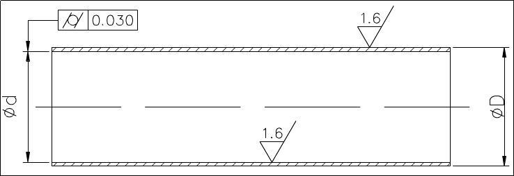
According to the technical requirements provided in the drawing, the workpiece is processed by seamless steel pipe, and the surface roughness of the inner hole and outer wall is Ra1.6 μ m. It can be realized by turning, but the cylindricity of the inner hole is 0.03mm, which requires high requirements for thin-walled parts. In mass production, the process route is rough as follows: blanking - heat treatment - turning end face - turning excircle - turning inner hole - quality inspection.
"Inner hole machining" process is the key to quality control. It is difficult to ensure a 0.03mm cylinder when cutting the inner hole of a shell without a cylindrical thin wall.
Key technologies for turning holes
The key technology of turning holes is to solve the problems of rigidity and chip removal of inner hole turning tools. In order to improve the rigidity of the inner hole turning tool, the following measures should be taken:
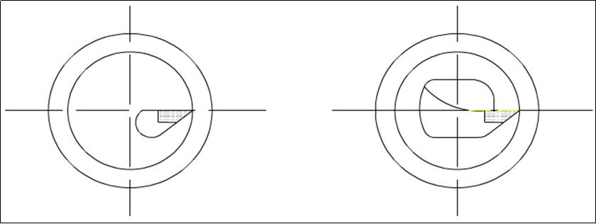
1) Increase the cross-sectional area of the tool handle as much as possible. Generally, the tip of the internal hole turning tool is located above the tool handle, so the sectional area of the tool handle is less than 1/4 of the sectional area of the hole, as shown in the following figure. If the tip of the inner hole turning tool is located on the center line of the tool handle, the sectional area of the tool handle in the hole can be greatly increased, as shown in the following figure.
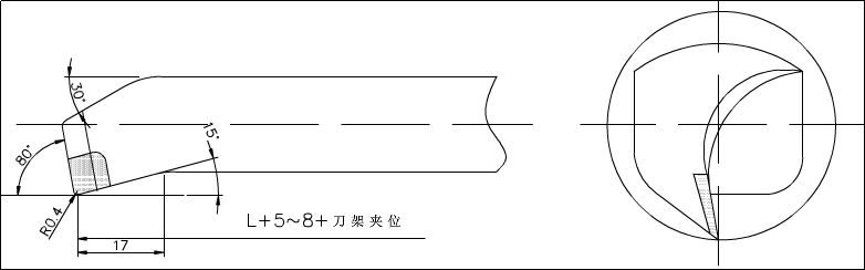
2) The extended length of the tool handle shall be 5-8mm longer than the length of the workpiece as far as possible to increase the rigidity of the tool handle and reduce the vibration during cutting.
Solve the problem of chip removal
It mainly controls the cutting flow direction. Rough turning tools require that the chip flows to the surface to be machined (front chip). Therefore, use the inner hole turning tool with positive edge inclination, as shown in the following figure.
In the process of fine turning, the chip flow direction is required to tilt the front chip towards the center (chip removal at the hole center). Therefore, attention should be paid to the grinding direction of the cutting edge when sharpening the tool. The chip removal method should follow the inclined arc forward. As shown in the figure below, the current M-type fine turning tool alloy YA6 has good bending strength, wear resistance, impact toughness, adhesion with steel, and temperature resistance.
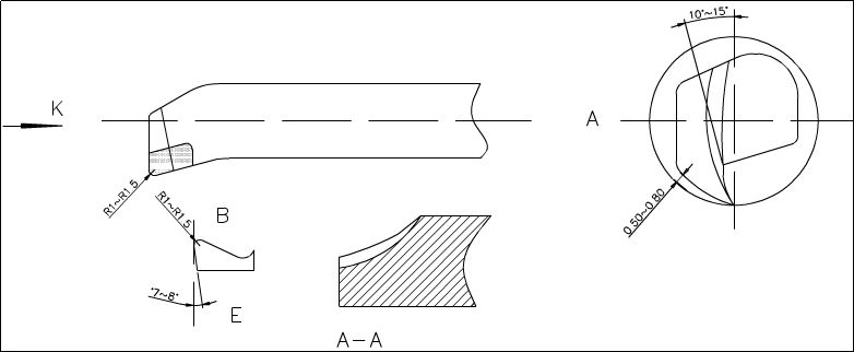
During grinding, according to the processing arc (along the arc of the tool bottom line), the front angle is rounded to an arc angle of 10-15 °, and the back angle is 0.5-0.8mm from the wall. The cutting edge angle of c is § 0.5-1 in the k direction and R1-1.5 at point B along the chip edge. The secondary rear angle is suitable for grinding to 7-8 °. Grind point A-A on the inner edge of E into a circle to discharge the debris outwards.
Processing method
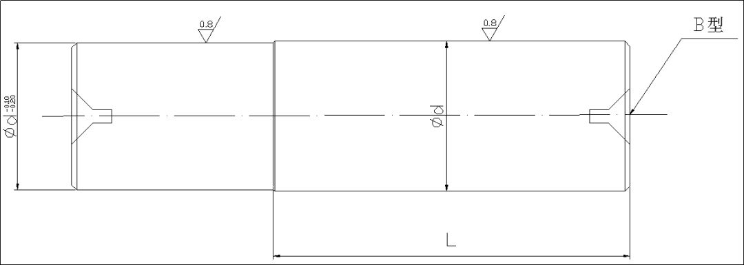
1) Shaft shields must be made before machining. The main function of the shaft protector is to cover the turning inner hole of the thin-walled sleeve with the original size and fix it with the front and rear centers, so that it can process the outer circle without deformation, and maintain the processing quality and accuracy of the outer circle. Therefore, the processing of protecting shaft is the key link of thin-walled casing processing.
45 # carbon structural round steel for processing rough embryo of retaining shaft; Rotate the end face, open the B-shaped central holes at both ends, make the outer circle rough, and leave 1mm allowance. After heat treatment, quenching and tempering, reshaping, and fine turning, a 0.2mm allowance shall be reserved for grinding. The crushed flame surface shall be subject to heat treatment again with a hardness of HRC50, and then ground with a cylindrical grinder, as shown in the following figure. The accuracy shall be satisfactory and shall be readily available upon completion.
2) In order to complete the processing of the workpiece at one time, the rough embryo should have a clamping position and cutting allowance.
3) First of all, after heat treatment, tempering, and molding, the hardness of the wool embryo is HRC28-30 (within the machining range).
4) The turning tool is C620. First, place the front center in the spindle cone for fixation. In order to prevent deformation of the workpiece when clamping the thin-walled sleeve, an open-loop thick sleeve is added, as shown in the following figure
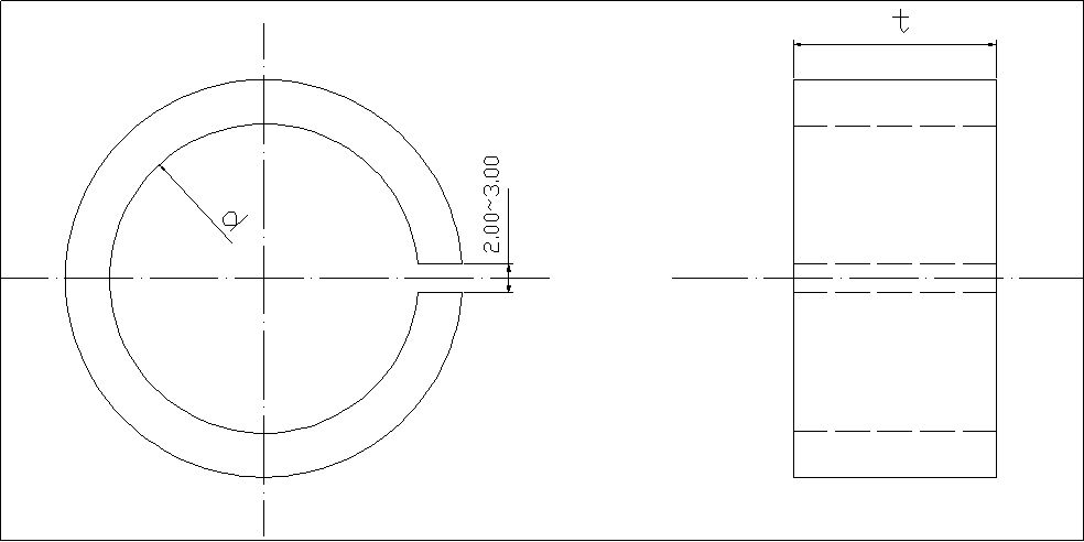
In order to maintain mass production, one end of the outer ring of the thin-walled shell is processed to a uniform size d, the ruler is clamped axially, and the thin-walled shell is compressed when rotating the inner hole to improve the quality and maintain the size. Considering the cutting heat, it is difficult to master the expansion size of the workpiece. Sufficient cutting fluid shall be injected to reduce the thermal deformation of the workpiece.
5) Clamp the workpiece with an automatic centering three jaw chuck, rotate the end face, and rough machine the inner circle. The finish turning allowance is 0.1-0.2mm. Replace the finish turning tool to process the cutting allowance to meet the requirements of interference fit and roughness of the protective shaft. Remove the inner hole turning tool, insert the guard shaft into the front center, clamp it with the tailstock center according to the length requirements, replace the cylindrical turning tool to rough the excircle, and then finish turning to meet the drawing requirements. After passing the inspection, use the cutting knife to cut according to the required length. In order to make the cutting smooth when the workpiece is disconnected, the cutting edge shall be tilted and ground to make the end face of the workpiece smooth; A small portion of the guard shaft is used to cut the gap and grind it smaller. The protective shaft is used to reduce the deformation of the workpiece, prevent vibration, and cut off the causes of falling and bumping.
Konclusion
The above thin-walled casing processing method solves the problem that the thin-walled casing deformation or size and shape errors cannot meet the requirements. The practice proves that this method has high machining efficiency, and convenient operation, and is suitable for machining long and thin wall parts. The size is easy to master, and the batch production is more practical.
Post time: Sep-29-2022


