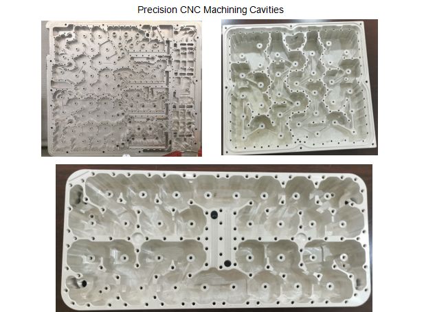
Custom Precision CNC Machined Filter Cavity


CAVITY RF FILTERS: WHAT THEY DO
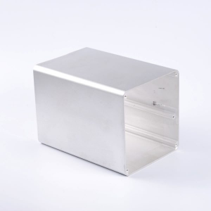
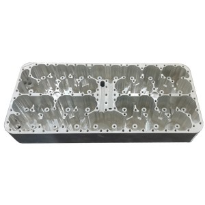
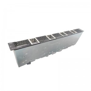
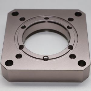
They typically consist of larger metal blocks with fewer RF connectors (2 for filters and 3 for duplexers that combine Tx and Rx signals into a single antenna port). As shown in the image below, these filters feature numerous screws on one or more sides of their bodies. Some of these screws are tuning screws, while others are used to fasten the top plate to the chassis.
In order to reduce RF losses and achieve the high Q or filter selectivity required to obtain low losses throughout the filter passband and sharp rejection outside of the filter passband, the aluminum body is always plated (with silver, copper, or even gold, but only for space applications).
In all wireless networks from 1G to 5G, as well as in civilian and military communication systems, RF Cavity Filters have been and continue to be the workhorse of the wireless industry. They have a very wide frequency range, ranging from 50 MHz to more than 20 GHz. Due to their lower wavelengths, they become smaller as the frequency rises (the speed of light is constant and is calculated as the product of the RF signal frequency and its wavelengths).
Although the passband for the majority of popular applications is between 1% and 10% of the operating frequency, RF Cavity Filters offer a wide range of practical applications since their passband can vary from less than 0.5% to up to 20% of the operating frequency. In order to get the best receiver performance in a real RF environment, the majority, if not all, wireless systems use RF Cavity Filters between the Antenna and Radio (bandlimited the LNA input signal to reject lower and upper frequencies outside of the system performance).
As Tx signals are substantially louder than any receiver signals by 120 to 150 dB, RF Cavity Filters are also employed on the Tx signal to ensure that PA noise and emissions are bandlimited and do not affect themselves or any other sort of wireless system.